Serial console!
 A guy named Mike on Mastodon mentioned he was chasing an amber serial terminal, and I half-jokingly responded that if he finds one and they have more than one, I’d be interested too… and that I wasn’t even so picky on the phosphor colour, I’d even take one of the white, ex-public-library specials.
He came back saying he had just such a beast, only it wasn’t working, and if I felt like a drive down to Melbourne and knew someone who knew how to fix CRTs I could have it. Hey, that’s me! I know a little bit (not a lot) about fixing CRTs, and we just happened to be heading down to Melbourne in about a week.
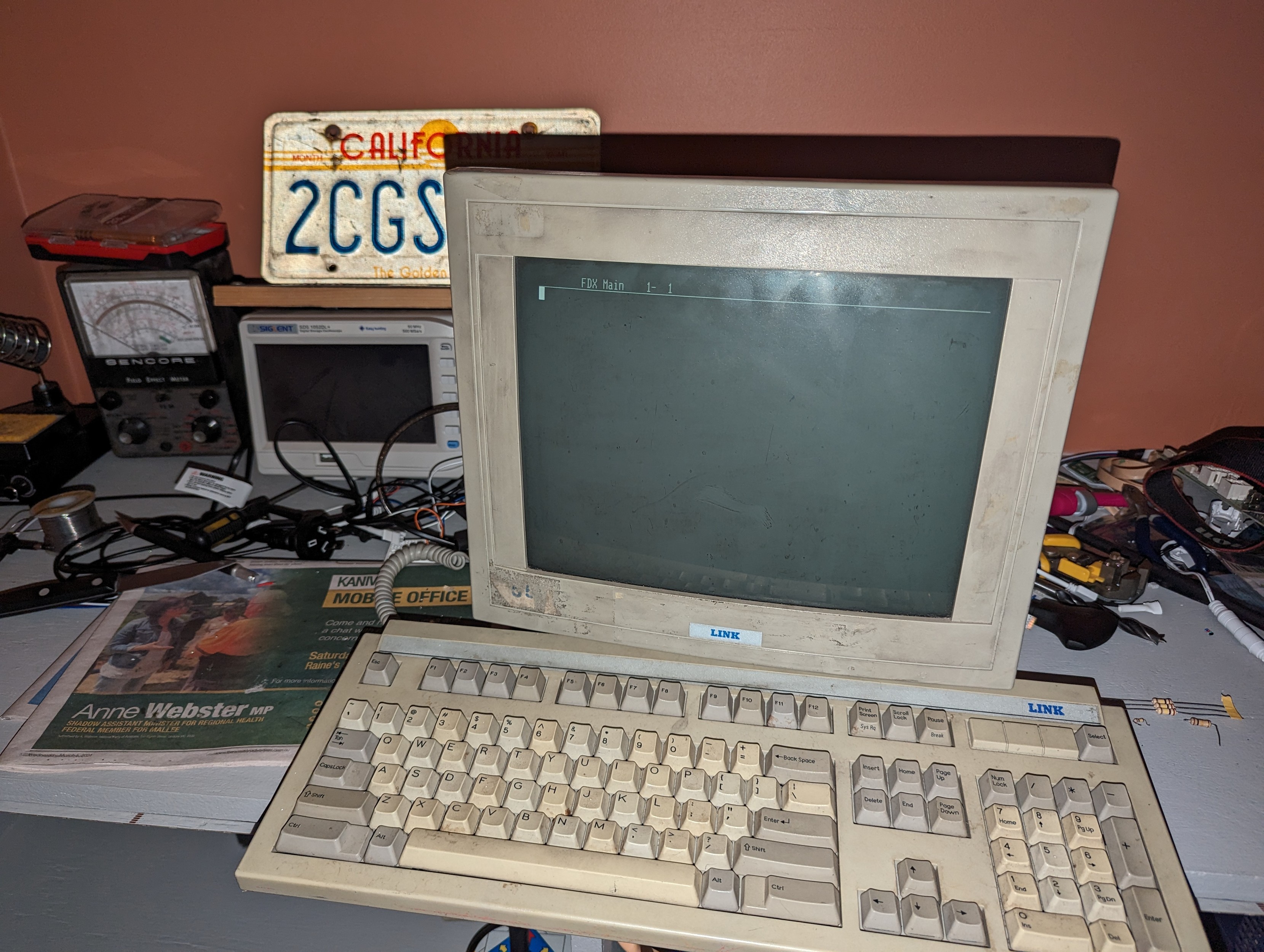
So on Saturday, we went down there and on the way met up with Mike. I left with not only the terminal (a Link MC3+ and a US-style keyboard), but he sent me off with a SunBlade 100 and a matching LCD monitor as well. I tried really hard to find some of the stuff I didn’t play with to trade, but he apparently has a back room full of stuff and can hardly move, and wouldn’t take anything.
We got home really early on Sunday morning, and on next to no sleep, I started poking at it. Noting that the tube didn’t make any noise or anything, I started from the beginning. The fuse was fine, the four diodes in the bridge rectifier checked fine. A memory deep in my subconscious bubbled to the surface and I remembered (I think I’m remembering this correctly?) that the first transistor nearest the AC side with the big honkin’ heatsink is the Horizontal Output Driver (or Transistor). The HOT is responsible for a bunch of stuff, but it also feeds the flyback, which could be responsible for the fact that nothing powers up?
But I don’t have the stuff to test a transistor, so I started poking the stuff around it. I found that there are two resistors that go between one of the DC rails and the base of the transistor, and one of them was open. I found a replacement that was the same resistance, but much tinier. I soldered it in temporarily and the machine lit up! So I picked up a replacement of the correct wattage.
Experimenting more, I figured out that either the keyboard wasn’t working or the thing was freezing. After some fooling around dumping data at it from my laptop, I figured out that the latter was not what was happening. I poked at the keyboard a bit with my oscilloscope, buzzed out the cable to make sure it’s correct… after a while I noted that the clock signal was significantly more sloppy with it plugged in, so I hazarded a guess that the issue was in the keyboard.
Taking it apart, I noticed what I thought was a leaky capacitor. That turned out to be hot glue, but I started tracing the circuit near it. I noted that on the signal and clock wires there were diodes in series with them, after a set of inductors/chokes/whatever, and then there were another set of diodes that went from the wire to ground. I’m not sure of the purpose of this, whether it’s for ESD protection, reverse-polarity protection, or what? But anyway, probing around them, I noticed that one of them was shorted!
So I desoldered it, found what looked like a similar one (appeared to be a 4148 glass diode), soldered it in and it works!
 fwaggle
Published:
Modified:
Filed under:
Location:
Horsham, VIC, AustraliaNavigation: Older Entry Newer Entry